Video
DCR-1006A Instructional Videos
This two-part video series provides a step-by-step guide to setting up and configuring the APG DCR-1006A controller for sensor control and monitoring. The DCR-1006A is a versatile solution for on-site level monitoring and remote communication through APG’s Tank Cloud.
You’ll learn how to:
-
Wire DST, MNU, and MPX sensors using RS485 communication
-
Connect AC or DC power to the DCR-1006A
-
Configure relay trip points for applications like conveyor control
-
Set up level monitoring in tanks using 4–20 mA analog output
-
Adjust sensor sensitivity, blanking, and application modes for your needs
Whether you’re monitoring moving equipment or managing tank levels, this tutorial walks through practical examples and shows how to tailor the DCR-1006A for your application.
View Transcript
Part 1
“Thank you for choosing Automation Product Group’s DCR-1006A for your sensor control and monitoring. The DCR-1006A is the best choice for simple on-site level monitoring and also connects to APG’s Tank Cloud for remote online communication. Many options and configurations are available to customize settings for your unique application. In this video, we will demonstrate how to set up the DCR-1006A for common applications using RS485 and DST sensors, AC and DC power, and analog output with alarms.
Let’s begin by wiring a sensor to the DCR-1006A. Reference the sensor label for wiring information. Remove the lid from the DCR, then remove the four screws holding the top board in place and gently remove the top board. If you are using a DST sensor, locate the DST input terminals in the bottom right corner of the bottom board. Attach the red power wire to the positive terminal and the black power wire or ground to the negative terminal. If your DST has a coaxial cable output and your DCR-1006A is equipped with an RF connector, the sensor can be connected to this external connector.
If you are using a sensor which uses RS485 communication such as an MNU or MPX, connect the positive and negative power wires to the 24-volt and ground terminals, and the A and B communication wires to the RS485 sensor A and B terminals. Next, we will hook up power. The DCR-1006A is compatible with either AC power from 85 to 264 volts or DC power from 12 to 24 volts. Before installing the power wires, ensure they are disconnected from the power source. If using AC power, attach the live power wire (commonly black) to the ACL or positive terminal, the neutral power wire (commonly white) to the ACN or negative terminal, and the earth ground wire (commonly green and yellow) to the ground terminal. If you are using DC power, the positive and negative terminals should match the outputs from your power supply.
Once the sensor and power wires are connected, reinstall the top board and turn on or plug in the power supply. The DCR’s LCD screen should turn on and the sensor should start audibly ticking. Ensure the DCR displays the distance reading from the sensor. If you are using an RS485 sensor, use the keypad to access Input Select from the Basic Menu and select RS485. From this point, the setup process will vary depending on the specific needs of your application. For this demonstration, we will set up the sensor to read distance. This type of setup is useful in areas with moving parts, such as monitoring the location of a moving arm on a conveyor and using relay trip points to change the action of the machine.
For example, let’s set up a sensor to monitor a target and run motors to make it move between five and ten feet from the sensor. First, determine the distance from the sensor to the nearest point you want your target to reach—five feet for this example. Using the keypad, navigate to the Basic Menu, find the Units option, and change it to feet. The trip point setup options are located in the Output Menu. The Trip 1 value (shown as TRIP 1V) sets the first actuation point of the relay—five feet for this example. The Trip Window (TRIP 1W) sets the difference from the Trip 1 value to the secondary actuation point. Since we want the sensor to stop at ten feet, we will set this value to five feet as well.
The Trip Type (TRIP 1T) sets the type of trip point. We want this motor to activate when the target comes closer than five feet and remain on until it reaches ten feet. To set this up, we will use the Hysteresis Near (H NEAR). This type of trip will activate when the distance reading equals the trip value and stay on until it reaches the sum of the trip value and trip window. Once the target has reached ten feet from the sensor, the motor connected to the H NEAR trip point should deactivate. At this time, we want the secondary motor attached to the second trip point to activate to bring the target back. Since this motor will follow the same distances and trip points, we will set up the trip value and trip window (TRIP 2V and TRIP 2W) the same as Trip 1. To change the trip functions so the motor moves in the opposite direction, we will use the Hysteresis Far (H FAR) trip type for TRIP 2T. This will activate the motor when the distance reaches the sum of the trip value and trip window, and stay on until it reaches the trip value.
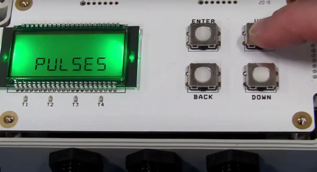
Sensor settings such as sensitivity and blanking can be found in the Ultra Menu. These settings may need to be adjusted depending on your application and environment. To wire external devices to the trip points, such as the motors in this example, locate the trip terminals on the DCR-1006A. Each trip output has a ground terminal and a choice between normally closed and normally open configuration. Since we want our motor to be on when the trip point is activated and off when the trip point is off, we will wire them to the NO, or normally open, position.
Another common application for the DCR-1006A is monitoring the level of material in a tank. For this example, let’s set up a sensor to monitor the level of water in a standard flat-bottom tank that stands ten feet tall. For this application, we will be calculating the level based on distance. To control the pump in our imaginary tank, we will be using an external current meter to monitor the level, so we will need to use the 4–20 milliamp output from the DCR-1006A. The 4–20 milliamp output is on an isolated circuit that must be powered in order to function.
To power the circuit from the 24-volt power source on the DCR, install a jumper from the 24-volt terminal to the 4–20 circuit’s voltage terminal. The 24-volt ground terminal will connect to the meter ground, and the 4–20 out terminal will connect to the meter’s milliamp input. If an isolated 4–20 output circuit is desired, simply connect the positive wire of your 9–28 volt DC power supply to the VS terminal. The negative power supply output should connect to the ground on the meter, and the 4–20 out terminal will connect to the positive milliamp input of the meter.
To set up the DCR-1006A for level monitoring, access the Application Type menu (APP TY) to change the mode to Level. Now, as the target moves closer to the sensor, the sensor reading will increase to reflect the greater volume of material being detected. Set the empty distance to ten feet and the full distance to one foot in the Level Mode menu. The current output from the DCR-1006A is set separately from the application type. To change current output settings, access the Output Menu. SET4MA and SET20MA correspondingly set the low and high current output set points. CAL4MA and CAL20MA are used to fine-tune the current output readings. It should not be necessary to adjust the calibration parameters. To set the current output to correspond to the distance readings on the DCR-1006A, set the SET4MA setting to ten feet and the SET20MA to one foot. If necessary, calibrate the output points using the CAL4MA and CAL20MA functions.
These are just a couple of ways that the DCR-1006A can be set up and customized for your sensor controlling and monitoring needs. With other functionalities such as customizable tank dimensions for level monitoring and cloud capability, the DCR can be set up for almost any application. For more options and information, check out our website at
Thank you for choosing Automation Product Group’s DCR-1006A for your sensor control and monitoring. The DCR-1006A is the best choice for simple on-site level monitoring and also connects to APG’s Tank Cloud for remote online communication. Many options and configurations are available to customize settings for your unique application. In this video, we will demonstrate how to set up the DCR-1006A for common applications using RS485 and DST sensors, AC and DC power, and analog output with alarms.
Let’s begin by wiring a sensor to the DCR-1006A. Reference the sensor label for wiring information. Remove the lid from the DCR, then remove the four screws holding the top board in place and gently remove the top board. If you are using a DST sensor, locate the DST input terminals in the bottom right corner of the bottom board. Attach the red power wire to the positive terminal and the black power wire or ground to the negative terminal. If your DST has a coaxial cable output and your DCR-1006A is equipped with an RF connector, the sensor can be connected to this external connector.
If you are using a sensor which uses RS485 communication such as an MNU or MPX, connect the positive and negative power wires to the 24-volt and ground terminals, and the A and B communication wires to the RS485 sensor A and B terminals. Next, we will hook up power. The DCR-1006A is compatible with either AC power from 85 to 264 volts or DC power from 12 to 24 volts. Before installing the power wires, ensure they are disconnected from the power source. If using AC power, attach the live power wire (commonly black) to the ACL or positive terminal, the neutral power wire (commonly white) to the ACN or negative terminal, and the earth ground wire (commonly green and yellow) to the ground terminal. If you are using DC power, the positive and negative terminals should match the outputs from your power supply.
Once the sensor and power wires are connected, reinstall the top board and turn on or plug in the power supply. The DCR’s LCD screen should turn on and the sensor should start audibly ticking. Ensure the DCR displays the distance reading from the sensor. If you are using an RS485 sensor, use the keypad to access Input Select from the Basic Menu and select RS485. From this point, the setup process will vary depending on the specific needs of your application. For this demonstration, we will set up the sensor to read distance. This type of setup is useful in areas with moving parts, such as monitoring the location of a moving arm on a conveyor and using relay trip points to change the action of the machine.
For example, let’s set up a sensor to monitor a target and run motors to make it move between five and ten feet from the sensor. First, determine the distance from the sensor to the nearest point you want your target to reach—five feet for this example. Using the keypad, navigate to the Basic Menu, find the Units option, and change it to feet. The trip point setup options are located in the Output Menu. The Trip 1 value (shown as TRIP 1V) sets the first actuation point of the relay—five feet for this example. The Trip Window (TRIP 1W) sets the difference from the Trip 1 value to the secondary actuation point. Since we want the sensor to stop at ten feet, we will set this value to five feet as well.
The Trip Type (TRIP 1T) sets the type of trip point. We want this motor to activate when the target comes closer than five feet and remain on until it reaches ten feet. To set this up, we will use the Hysteresis Near (H NEAR). This type of trip will activate when the distance reading equals the trip value and stay on until it reaches the sum of the trip value and trip window. Once the target has reached ten feet from the sensor, the motor connected to the H NEAR trip point should deactivate. At this time, we want the secondary motor attached to the second trip point to activate to bring the target back. Since this motor will follow the same distances and trip points, we will set up the trip value and trip window (TRIP 2V and TRIP 2W) the same as Trip 1. To change the trip functions so the motor moves in the opposite direction, we will use the Hysteresis Far (H FAR) trip type for TRIP 2T. This will activate the motor when the distance reaches the sum of the trip value and trip window, and stay on until it reaches the trip value.
Sensor settings such as sensitivity and blanking can be found in the Ultra Menu. These settings may need to be adjusted depending on your application and environment. To wire external devices to the trip points, such as the motors in this example, locate the trip terminals on the DCR-1006A. Each trip output has a ground terminal and a choice between normally closed and normally open configuration. Since we want our motor to be on when the trip point is activated and off when the trip point is off, we will wire them to the NO, or normally open, position.
Another common application for the DCR-1006A is monitoring the level of material in a tank. For this example, let’s set up a sensor to monitor the level of water in a standard flat-bottom tank that stands ten feet tall. For this application, we will be calculating the level based on distance. To control the pump in our imaginary tank, we will be using an external current meter to monitor the level, so we will need to use the 4–20 milliamp output from the DCR-1006A. The 4–20 milliamp output is on an isolated circuit that must be powered in order to function.
To power the circuit from the 24-volt power source on the DCR, install a jumper from the 24-volt terminal to the 4–20 circuit’s voltage terminal. The 24-volt ground terminal will connect to the meter ground, and the 4–20 out terminal will connect to the meter’s milliamp input. If an isolated 4–20 output circuit is desired, simply connect the positive wire of your 9–28 volt DC power supply to the VS terminal. The negative power supply output should connect to the ground on the meter, and the 4–20 out terminal will connect to the positive milliamp input of the meter.
To set up the DCR-1006A for level monitoring, access the Application Type menu (APP TY) to change the mode to Level. Now, as the target moves closer to the sensor, the sensor reading will increase to reflect the greater volume of material being detected. Set the empty distance to ten feet and the full distance to one foot in the Level Mode menu. The current output from the DCR-1006A is set separately from the application type. To change current output settings, access the Output Menu. SET4MA and SET20MA correspondingly set the low and high current output set points. CAL4MA and CAL20MA are used to fine-tune the current output readings. It should not be necessary to adjust the calibration parameters. To set the current output to correspond to the distance readings on the DCR-1006A, set the SET4MA setting to ten feet and the SET20MA to one foot. If necessary, calibrate the output points using the CAL4MA and CAL20MA functions.
These are just a couple of ways that the DCR-1006A can be set up and customized for your sensor controlling and monitoring needs. With other functionalities such as customizable tank dimensions for level monitoring and cloud capability, the DCR can be set up for almost any application. For more options and information, check out our website at apgsensors.com.”
Part 2
“The DCR-1006A is a versatile display and controller designed for use with APG’s DST, MNU, and MPX sensors. Because of the DCR-1006A’s wide range of functionality, settings may need to be changed to optimize the unit for your specific sensor and application. If you encounter an error code during setup, this video serves as a troubleshooting guide to help identify and remedy the problem. Different error codes designate different failures. In this video, we will cover what the various error codes mean, along with potential causes and solutions.
The DCR-1006A is equipped with a failsafe designed to prevent sensor damage from an electrical short. An E1 error code means a short-circuit has been detected in the DST sensor line, and power to the sensor has been interrupted to prevent damage. The most common cause of this failure is sensor wires inadvertently making contact, which may occur due to wire fraying or excessive insulation being stripped from the wire, allowing contact between bare wires. Use caution when installing wires, ensuring all strands are twisted and properly secured in the connector. Strip wire ends so the insulation covers the wires as close to the connector as possible without being pinched. To prevent damage, always verify that your power supply is compatible and that the wiring of the DCR and all components is correct before applying power. For more details, see DCR-1006A Instructional Video #1 for a guide to powering your unit.
An E2 error is displayed when the DCR-1006A is not communicating with the selected sensor. For DST sensors, communication failure may be caused by damage to components on the positive power line due to exposure to excessive power. This issue may be diagnosed by checking the current draw of the sensor. While low or no current draw does not rule out this type of damage, a high current draw over 100 milliamps indicates damaged components. The most common cause of communication failure is improper setup. First, check the DCR’s communication settings by accessing the Basic Menu and Input Select submenu, verifying that the setting matches the sensor you are trying to communicate with. If the DCR is set up for RS485 communication while you have a DST sensor installed—or vice versa—the devices will not communicate. Always double-check sensor wiring before powering the sensor, as incorrect wiring can prevent communication and potentially damage the sensor. If you are using an RS485 sensor, make sure the sensor address is set to Address 1, since the DCR-1006A can only communicate with a sensor at this address. You can change the Modbus address of the DCR-1006A by accessing the Basic Menu and Sensor Number submenu. If you have verified correct setup but still cannot establish communication, test the sensor directly with your RS485 connection and computer. If the sensor successfully communicates with another device, the DCR-1006A may be damaged. In this case, please contact the factory for technical support.
An E3 error indicates a loss of echo, meaning the sensor is communicating with the DCR-1006A but cannot acquire a target. This failure commonly occurs due to installation or setup issues. To avoid this error, ensure that the sensor is mounted perpendicular to your target; deviations of more than five degrees may prevent detection. Ideal target surfaces are hard and smooth, while materials that absorb sound waves will reduce operating range and accuracy. These factors become increasingly important as the distance between the sensor and target grows. Sensitivity and pulse settings can be adjusted for better target acquisition. For sound-absorbing targets, increase these settings for a stronger ultrasonic pulse. Conversely, if the sensor is mounted in a tank prone to echoing, lower these settings for more precise readings. There should always be a three- to four-foot diameter column of unobstructed air between the sensor and target. Mount the sensor away from fill spouts to avoid false readings from splashing or sloshing. If the tank has a domed top, avoid mounting the sensor at the center of the dome, as this can create echoes that cause target loss. Similarly, avoid placing the sensor too close to tank walls, which may inadvertently be detected as targets.
The distance from the sensor to the closest possible target should always be greater than the blanking distance. In applications where headroom does not allow this, a standpipe can be used to mount the sensor above the tank. The standpipe should be smooth and straight with no joints, burrs, or obstructions. Ideally, its diameter should be half its length, and the end of the pipe should be cut at a 10- to 45-degree angle. In areas that are difficult to access or prone to sloshing liquid or foam buildup, a stilling pipe may be used to provide a better target for the sensor. However, this solution is only suitable for liquid targets that do not leave deposits. A vent hole must be included above the liquid level but inside the blanking distance. Since a stilling pipe greatly reduces the target area, sensitivity and pulse settings will likely need to be reduced to prevent unwanted echoes.
Environmental conditions such as temperature, humidity, vapors, dust, and pressure can affect sensor performance. APG sensors are built to compensate for many of these factors; however, in extreme conditions you may need a sensor rated for longer ranges than would normally be required. Environments with heavy chemical vapors such as solvents or gasoline, heavy dust, or excessive surface foam may not be suitable for ultrasonic sensors. For additional troubleshooting help, please contact APG technical support.”