Video
How To Set Up the MNU IS
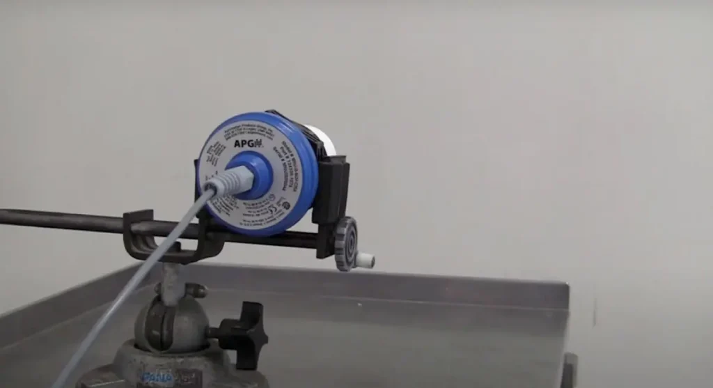
This video walks through the setup for the MNU IS ultrasonic level sensor by APG. The MNU IS is CSA and ATEX certified, with optional lightning protection, making it a reliable choice for a wide range of applications. We’ll cover how to configure key parameters such as units, application type, full and empty distances, sensitivity, pulses, gain control, averaging, and sample rate. You’ll also learn how to use QuickMode for fast readings, adjust settings for accuracy, and reset the sensor to factory defaults if needed. Finally, we’ll show how to integrate the sensor with APG’s Tank Cloud for remote monitoring and alarms.
View Transcript
“Thank you for choosing the MNU IS from Automation Products Group for your sensor needs. The MNU IS is the result of extensive research into Modbus utility, intrinsic safety, and customer needs, and APG is proud to present the perfect sensor for your application. The MNU IS is CSA and ATEX certified and is even available with optional lightning protection. In this video, we will show many of the basic functions of the sensor and how to set it up for your application. To begin, check out our instructional video on APG Modbus for help hooking up your sensor and setting up communication with APG Modbus. Once you have successful communication with your sensor, we can begin at the top of the parameters list.
The Units parameter sets the unit of measurement the sensor will use to display readings if set in distance mode. Application types 0, 1, and 7 are calculated in distance mode. The Application Type parameter determines how the sensor will calculate readings: if type 0, 1, or 7 are selected, readings are calculated using distance mode, while types 2–6 and 9–11 use volume mode. The Volume Units parameter sets the unit of measurement the sensor will use to display readings if set in volume mode.
The Decimal Place parameter determines how the reading from the sensor will be rounded. For instance, if the sensor reads 1.293 meters and the decimal place is set to 0, the display will show 1 meter. If the decimal place is set to 3, the full value of 1.293 will be displayed. The Max Distance parameter determines the distance at which the sensor will no longer accept readings. The sum of the max distance and the offset cannot exceed the maximum operating range of the sensor.
The Full and Empty Distance parameters are designed for monitoring tank levels and set the distances from the sensor’s zero point that the vessel is considered full or empty. The full distance parameter must be set to a value equal to or greater than the blanking distance, while the empty distance must be less than the max distance for the sensor to accept readings when the vessel is empty. Sensitivity sets the level of gain applied to the sensor signal. In AutoSense, Hard-Target, or Soft-Target modes, this parameter sets an upper limit to the gain that can be applied. If the sensor is operated in manual mode, the value will set the gain directly. It is recommended to determine the minimum gain that allows reliable tracking across expected conditions, which will save power and extend sensor life.
The Pulses parameter sets the number of ultrasonic pulses per transmission. More pulses create a stronger echo, useful in damping environments, while fewer pulses help reduce multiple echoes in acoustically active or enclosed environments. Blanking Distance is the distance from the zero point of the sensor from which the first echo will be accepted. This is often used in stand pipe installations or to ignore unwanted targets close to the sensor.
Gain Control allows you to choose between automatic and manual gain settings. In AutoSense, sensitivity and pulses are automatically optimized. In Hard-Target or Soft-Target mode, the sensor uses the entered sensitivity and pulses as limits. In manual mode, all changes must be made by the user. Averaging, Filter Window, Out of Range, and Sample Rate parameters stabilize readings. Averaging determines how many signals are calculated into the displayed value. The Filter Window sets the allowed difference between readings to be accepted. The Out of Range parameter determines how many consecutive out-of-window readings are needed before the sensor updates. Sample Rate sets the delay between samples, where shorter delays increase responsiveness but longer delays reduce false positives and extend sensor life.
For example, with default settings, the sensor averages 10 readings, accepts values within 50 millimeters, and requires 10 out-of-range readings before updating. This results in a response time of about 3 seconds. Reducing averaging and out-of-range values speeds the response to about 1 second, while increasing them makes the sensor less prone to false positives but slower to respond, around 5 seconds.
The Multiplier parameter adjusts for changes in the speed of sound due to atmospheric variations. To calibrate, aim the sensor at a known target near its maximum range and adjust the multiplier until the displayed distance matches the known distance. Offset sets the point from which distance is calculated, either at the transducer face (0), forward toward the target (positive), or behind the sensor face (negative). Blanking is measured from the offset point. Temperature Compensation automatically adjusts the multiplier for temperature effects.
QuickMode provides fast distance readings by averaging a set number of samples immediately after power-up, with a programmable delay. For example, setting the QuickMode Delay to 750 milliseconds results in a reading 500 milliseconds after power-up is complete. Before using QuickMode, optimize all sensor settings, including blanking, sensitivity, and pulses, to ensure reliability. Once enabled, the sensor takes the programmed samples, enters low-power mode, and displays the average. Resampling can be triggered via registers or by power cycling the sensor.
Pulse Power functions as a secondary gain control, setting transmission power independently of Gain Control. The QuickMode Resample holding register can trigger new samples when a value other than 0 is written. If needed, you can reset your MNU IS to factory defaults via the Tools tab.
Trip value, window, and type can be configured to create outputs in input registers. These are not physical alarms but can be monitored by a controller, such as APG’s Tank Cloud system or another RS-485 interface, to trigger alarms.
If you need help setting up your MNU IS or are interested in remote monitoring through Tank Cloud, please contact APG’s application engineers at (435) 753-7300 or visit apgsensors.com.”