Video
How to Setup Your Sensor with APG Modbus
In this video, we will demonstrate how to set up communication for several types of sensors with APG Modbus, as well as the settings you can use to customize your sensor for your application.
View Transcript
“Thank you for choosing Automation Products Group for your sensor and monitoring needs. If you’ve purchased an RS-485 sensor from APG, you already know that the versatility and convenience of sensor interface communication is invaluable in today’s increasingly automated industries. The ability to monitor and log readings, and adjust sensor settings from a network location, saves both time and money. APG Modbus is the hub for RS-485 communication with your sensors, allowing you to change everything from communication baud rate to custom labels. In this video, we demonstrate how to set up communication for several types of sensors, as well as the settings you can use to customize your sensor for your application.
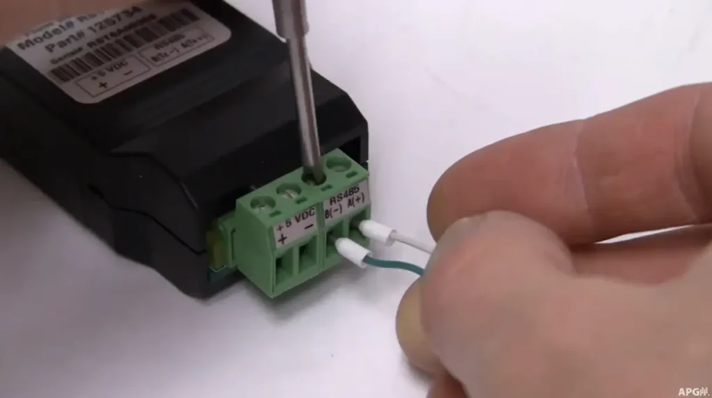
To communicate with APG Modbus, several APG products—such as the RST interface series or the DCR-1006A—are available with RS-485 communication. The RST-4100 is designed for use with an MPX sensor with HART communication, and a variety of other RS-485 USB adapters are also available from other manufacturers. To begin, check your sensor wiring information and wire the sensor to your RS-485 communication device according to the A-B wiring configuration. Your sensor must also be powered, either with an external power supply or, in the case of a DCR-1006A, with the included 24-volt power line. If wiring an MPX, a 120-ohm resistor must be installed between the A and B terminals of the sensor—or, for multiple MPX sensors in a daisy chain, at the last sensor in the chain. If using a communication device other than an RST-6001, you must also install a 120-ohm resistor between the A and B terminals of the RS-485 device, though the RST-6001 has this internally. When programming an MPX with 4–20 milliamp output, a 150–700 ohm load resistor must be installed in series between the RST and the positive power terminal.
Upon opening APG Modbus, begin by setting up your communication based on the sensor you’re using. In the Configure tab under Communication, select your sensor type from the drop-down menu. You can also set the number of sensors and assign new address numbers. Note that the default sensor address is 1, and any changes to the sensor address must first be made in the sensor parameters before being updated in the configuration screen. On the left side of the menu, you can select USB or Comm port and choose your serial setup options. APG sensors typically use 9600 baud rate, no parity, and 1 stop bit. MPX sensors can only communicate at 9600 baud. Be sure to save your configuration after changes. For setups with more than one sensor, use the Quick Start guide under the Help tab.
Once your communication configuration is complete, return to the main screen and click Start Communication. If successful, the parameter screen will update with values highlighted in green and display “Comm Good.” If it shows “Comm Bad,” check your wiring and sensor address. With communication established, you can now set up parameters for your application. These will vary depending on sensor type, so consult the parameter descriptions in APG Modbus and your sensor’s manual. To change a parameter, update the Value column, click Send, and confirm that the register row turns blue. To change a sensor address, update the parameter, click Send, then adjust the communication screen to match the new address and save the configuration.
Parameters for level applications—such as empty, full, and max—must be entered in millimeters, while pressure applications require PSI. Register 300 displays the raw sensor output, while Register 303 displays the calculated output based on your chosen parameters. Some RS-485 devices also provide analog output, which can be configured in APG Modbus with the 4 and 20 milliamp setpoints. Fine-tuning can be done with the 4 and 20 Cal parameters, though these are factory-set and usually do not need changes. Note that register addresses in APG Modbus may differ when read through other RS-485 interfaces such as PLCs, since APG Modbus begins addressing at 1. For example, calculated sensor output at address 303 in APG Modbus would be read as 302 in a PLC. If you experience communication or setup issues, please contact APG’s Application Engineers at 877-373-5940. Additional resources, including live chat, can be found at apgsensors.com.”